Transformer wiring diagram
In standard design the terminals of ELEQ current transformers are marked according to IEC. Please find some transformer wiring diagrams below:
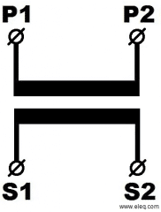
Transformer wiring diagram for single ratio current transformer.
100/5 A
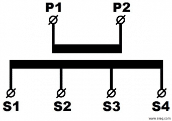
Multi ratio current transformer, with an intermediate tapping on secondary winding. The output of the transformer decreases proportionally with the ratio.
(150-200-300) /5A S2 = 150/5A S3 = 200/5A S4 = 300/5A
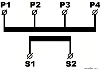
Multi ratio current transformer, with an intermediate tapping on primary winding. The output of the transformer remains constant for all ratio’s.
(60;30;20) / 5A P2 = 60/5A P3 = 30/5A P4 = 20/5A
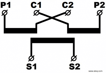
Transformer with primary winding in 2 sections intended for connection either in series or parallel.
(2 x 10)/5 A Serie = 10/5A Parallel = 20/5A
Summation current transformers with several separated primary windings.
((300)5 + (200)5) / 5A A P1 – A P2 = (300)5A, B P1 – B P2 = (200)5A
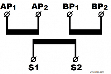
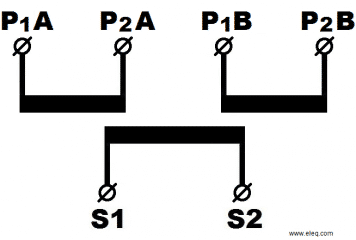
Current transformer with several separated primary windings. Primary currents will be added.
(15/10 ) / 5A (PA/PB/S) P1 A –P2 A = 15/5A, P1 B –P2 B = 10/5A
One coil current transformer with several intermediate primary and/or secondary tappings. The primary and secondary circuit are not separated.
10; 5; 2,5A (P2; S2; P3)
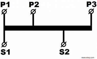
Unused primary or secondary taps remain open.
Busbar
Window type current transformers of standard design are provided with fastening clamps for the busbar. The RM series transformers are supplied with busbar fastening clamps integrated in the casing (made of unbreakable polycarbonate). The stepped design of the busbar opening permits application of several busbars in one model. Fastening feet are supplied standard.
The busbar attachment for the transformers of the RM series is integrated into the transformer housing. All transformers from the RM series are provided with fastening feet.
The current transformers are designed for a 720V line voltage and can therefore be mounted, without the need for further insulation, in mains up to that voltage. On request ELEQ current transformers can be supplied for use at line voltage of up to 1200V. The requisite test voltage is 6 kV.
However, low voltage window type current transformers can also be used in medium and high voltage mains, provided that the busbar of cable is insulated for that voltage. The open design transformers and the larger cast resin type transformer models are ideally suited for this particular application.
In mains up to approximately 1000A the position of the primary conductor in the busbar opening hardly affects the measuring accuracy of the current transformer. For 1000A and up the current transformer must be mounted on the centre of the busbar.
With currents of approximately 2000A and up, the return conductor of the adjacent phase conductor must be expected to affect the measuring accuracy, if the distance between this live conductor and the transformer case is roughly less than 1 cm/1000A rated current. This applies in particular to instrument transformers with low rated accuracy limit factor.
The measurement of very high amperages (> ≈10.000A) can be adversely affected by external magnetic fields, which may originate from the adjacent phase or from the return conductor. The same problem may arise when at such high amperage the conductor is passed asymmetrically through the busbar opening.
This adverse influence can be minimized by providing the transformer core with an additional compensating winding. The terminals of compensating winding are not led out.
The table below shows the admissible maximum current load on busbars at an ambient temperature of 35°C and a maximum final temperature of the busbar of 65°C.
Example: As shown in the table, the admissible current for a painted busbar 80 x 10 mm is 1500A. In the graph can be found the factor α with which the standard admissible current must be multiplied to obtain the new maximum current at different temperatures. For a final busbar temperature (Te) of 90°C and an ambient temperature (To) of 50°C, the factor α = 1,15, which can be read from this example. This means that the new allowed maximum current will be 1,15 x 1500A = 1725A.
With the aid below it is possible to compute the maximum admissible current for different ambient and final temperatures of the busbar.

 +31 (0)521 533 333





 EN
EN  NL
NL