Transformer wiki
Transformer ratio
This indicates the rated primary and secondary current, for example 200/5A. Standard values for the secondary current: 5A and 1A.
Rated output
This is the output Pu that can be delivered by the current transformer at the rated current (In), expressed VA. Relationship between external load Ru and rated output: Pu = In2 x Ru. The output will always be specified with the rated current.
Transformers will be bigger as a higher rated output is required.
Class
This is the current transformer’s accuracy class. Instrument transformers may, for example, have the class designation 3 or 0,2. Protective current transformers may have the class designation 5P.. or 10P.., followed by the requisite accuracy limit factor. Standard ANSI uses a different output and class designation, for example Class 0,6B-0,9 or Class C400.
Transformers will be bigger as a greater accuracy is required.
Accuracy limit factor
Instrument transformers for example Fs5 or M5. And for protective current transformers for example 20 for class 5P20.
Transformers will be bigger as a higher accuracy limit factor is required.
If Class X is specified:
For current transformers in Class X the minimum required kneepoint voltage Vk of the secondary winding must be specified.
Specification of the maximum exciting current lexc and the maximum resistance Rct of the secondary winding at 75°C is optional.
Maximum system voltage
The highest system voltage for standard current transformers is 0,72 kV (test voltage 3 kV). ELEQ low voltage insulated current transformers can also be used under medium and high voltage conditions, provided the user ensures adequate insulation between voltage-carrying conductor and transformer.
Rated short-time thermal current (lth)
The rated short-time thermal current (lth) of a transformer is, according to IEC, the r.m.s. value of the primary current which the transformer will withstand for one second without suffering harmful effects, the secondary winding being short-circuited.
The admissible rated short-time current is determined by the copper cross-section of the primary and secondary winding.
The correlation between the rated short-time thermal current (lth) and the admissible short-time current (lk) in connection with time (t) can be expressed in the following equation:
Ik = Ith / √(t )
t = duration of short-time current in seconds
Ith = rated short-time thermal current of the transformer
Ik = admissible short-time current
In standard design ELEQ current transformers will withstand a short-time thermal current of 60x rated primary current (max. 120kA). Higher short-time currents on request. According to NEN a dynamic current of 2,2 x Ith applies to rated currents of more than 3000A.
Rated dynamic current (Idyn)
The rated dynamic current (Idyn) of a transformer is, according to IEC the peak value of the primary current which a transformer will withstand, without being damaged electrically or mechanically by resulting electromagnetic forces, the secondary winding being short-circuited.
The admissible rated dynamic current is determined by the mechanical strength of the transformer.
In standard design ELEQ current transformers will withstand a dynamic current of 2,5x Ith.
The dynamic strength is not suitable for the fastening feet, which only serve to fasten the transformer to the construction. The dynamic forces in the busbars, due to a short-circuit must be held by the fastening construction of the busbars.
Low primary current
To obtain a current transformer with lower ratio than can be found in the tables, it is possible to fit the current transformer with a hand-made primary winding.
Another possibility is to choose a higher ratio than necessary in order to improve the output and/or accuracy, and to reduce the ratio to the desired value by fitting the current transformer with a handmade primary winding.
Example:
The current transformer type RM60-E2B, 100/5A, class 3, normally has an output of 7,5VA.
The same model 200/5A, class 3, has a rated output of 15VA. By fitting this model with a primary winding of 2 turns the ratio will be reduced to 100/5A. In spite of this the rated output of 15VA will be kept.
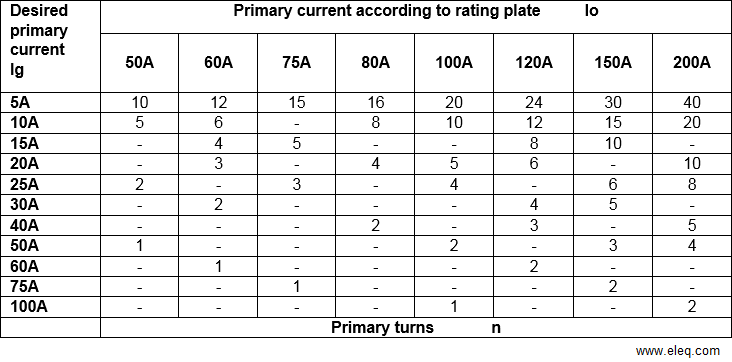
The necessary handmade primary turns (n) can be calculated by dividing the original ratio (lo) of the current transformer by the desired ratio (lg).
Io = original ratio
Ig = desired ratio
n = number of primary turns going through the busbar-opening of the current transformer.
Ip / Is = Ns / Np = Iprimary / Isecundary = Nsecundary / Nprimary = Io
Note: the ratio between the ratio of the original current transformer and the desired ratio must always be integer. It is not possible to fit ‘half turns’. The table below shows several possibilities:

Current error and phase displacement as function of the rated current

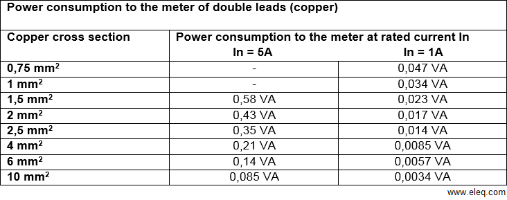
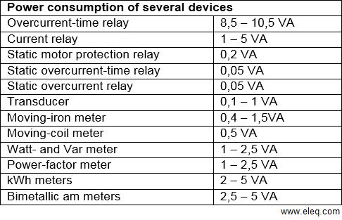
Power consumption of connected devices

The measuring accuracy of a current transformer is related to the connected burden. The standardization requirements laid down in IEC stat that the accuracy class is based on a connected load ranging from 25 to 100% of the rated burden indicated on the rating plate.

Short-circuit of secondary winding
On no account current transformers should be operated with open secondary winding, not even for a very short time. The reason is that the voltage across open terminals may rise to thousands of volts. This not only involves peril of life, but also the risk of the transformer insulation sustaining permanent damage.
When a current transformer is put in active operation without a connected burden, the secondary terminals of the current transformer always must be short-circuited with a piece of wire or a special short-circuit connector.
When there is one or more tapping on the secondary winding, it is sufficient only to short-circuit the full winding (highest transformation ratio); the other tappings may remain open. Obviously, of multi-core transformers the secondary winding of each core must be short-circuited individually.

 +31 (0)521 533 333


 EN
EN  NL
NL